

🔹 OSI Model #
The OSI model frequently confuses engineers and is often dismissed as a faded, abstract concept. In reality, it is the fundamental core of computer networking. Without it, a Backend or DevOps engineer simply cannot unlock their full potential. Terms like segments, packets, frames, and L4 vs. L7 load balancing dominate IT conversations, yet few truly grasp them. I previously set the stage for these concepts in my HTTPS and SSL article. This article bridges the remaining gaps by mastering the foundational layers.
I will try to explain it in the simplest way, using just a diagram.
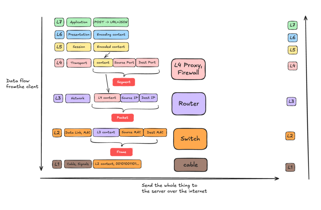
This diagram illustrates the data flow from a client application down through each OSI layer. As the data descends, you can see exactly how it is enriched at each stage—turning into Segments at L4, Packets at L3, and Frames at L2. The diagram also maps the specific network hardware (Proxies, Routers, and Switches) that handle these data units. Finally, the data travels across the physical medium (L1) and ascends the server’s network stack from Layer 1 up to the Layer 7 application to process the incoming POST request.
🔹 IP for Dummies #
CIDR Notation & Subnetting #
In networking, you will usually see IP addresses formatted like this: a.b.c.d/x. This is known as CIDR notation, and it is used to define the IP range of a subnet.
The /x shows you exactly how many bits are locked down for the network, and how many bits remain free for the hosts (devices) on that network.
Let’s say we have 192.168.1.0/24. An IPv4 address consists of 4 blocks (octets), and each block is exactly 8 bits, totaling 32 bits.
In binary, 192.168.1.0 looks like this:
11000000 . 10101000 . 00000001 . 00000000
The /24 means that the first 24 bits are frozen. They belong to the network and cannot change:
First 24 bits (FROZEN)          | Remaining 8 bits (FREE)
11000000 . 10101000 . 00000001  |  00000000
[------- 192.168.1 -------]     |  [-- 0 --]
Since the 24 bits are frozen, 32 – 24 = 8 so the total available hosts are 2^8 – 2 = 254.
Network ID: 192.168.1.0 – It represents the network and cannot be assigned to a host.
Broadcast Address: 192.168.1.255 – Data sent here goes to everyone in the network and no host can be assigned to it.
Network Mask: Defines the size of the subnet, often shown as 255.255.255.0 or /24. It is also used to determine if an IP is in the same subnet.
So 192.168.1.1 is the first usable host and 192.168.1.254 is the last usable host.
Use mask to determine if 2 IPs belong to the same subnet #
To find out if two IP addresses are in the same network, a computer performs a fast, elegant mathematical operation called a Bitwise AND.
Lets find out if IP: 192.168.1.5 and IP: 192.168.1.50 are in the same subnet.
IP 1 (Binary):    11000000 . 10101000 . 00000001 . 00000101  (192.168.1.5)
Mask (Binary):    11111111 . 11111111 . 11111111 . 00000000  (255.255.255.0)
----------------------------------------------------------- [Bitwise AND]
Network ID:       11000000 . 10101000 . 00000001 . 00000000  (192.168.1.0)
IP 2 (Binary): 11000000 . 10101000 . 00000001 . 00110010 (192.168.1.50)
Mask (Binary): 11111111 . 11111111 . 11111111 . 00000000 (255.255.255.0)
----------------------------------------------------------- [Bitwise AND]
Network ID: 11000000 . 10101000 . 00000001 . 00000000 (192.168.1.0)Both of the IP have the same network ID, so they belong to the same network, so same subnet.
Network Diagnostics (ICMP, Ping, and Traceroute) #
When things break at Layer 3, you need tools to figure out where the connection is dropping.
ICMP (Internet Control Message Protocol) is a helper protocol for the Internet Protocol (IP).
Unlike TCP or UDP, ICMP does not carry application payloads like web pages or file downloads. Instead, it is used by network devices to send error messages and operational information.
TTL: Despite its name, TTL is not measured in seconds or milliseconds. Instead, it is a hop counter that acts as a self-destruct timer for your network packet Every single time your packet passes through a router (a “hop”), that router decreases the TTL value by 1.
Ping: When you run ping 8.8.8.8, your computer wraps an ICMP Echo Request packet inside an IP packet and shoots it across the network. When the destination server receives it, it is obligated to wrap an ICMP Echo Reply packet and send it right back.
Traceroute: While ping tells you if you can reach a server, traceroute shows you the exact path your packet takes to get there. It maps every single router hop along the way. The genius of Traceroute is that it does not use a special protocol. Instead, it intentionally hacks the TTL (Time to Live) rule to force routers to talk to it. It starts with TTL = 1, the next available gateway descrements it to 0 and send back a reply with it’s IP. On the next ping it increments the TTL to 2 and when it reaches the next available gateway after the previous one, the TTL goes also to 0 so now we know the second hop (router) IP.
🔹 TCP, Sockets & file descriptors #
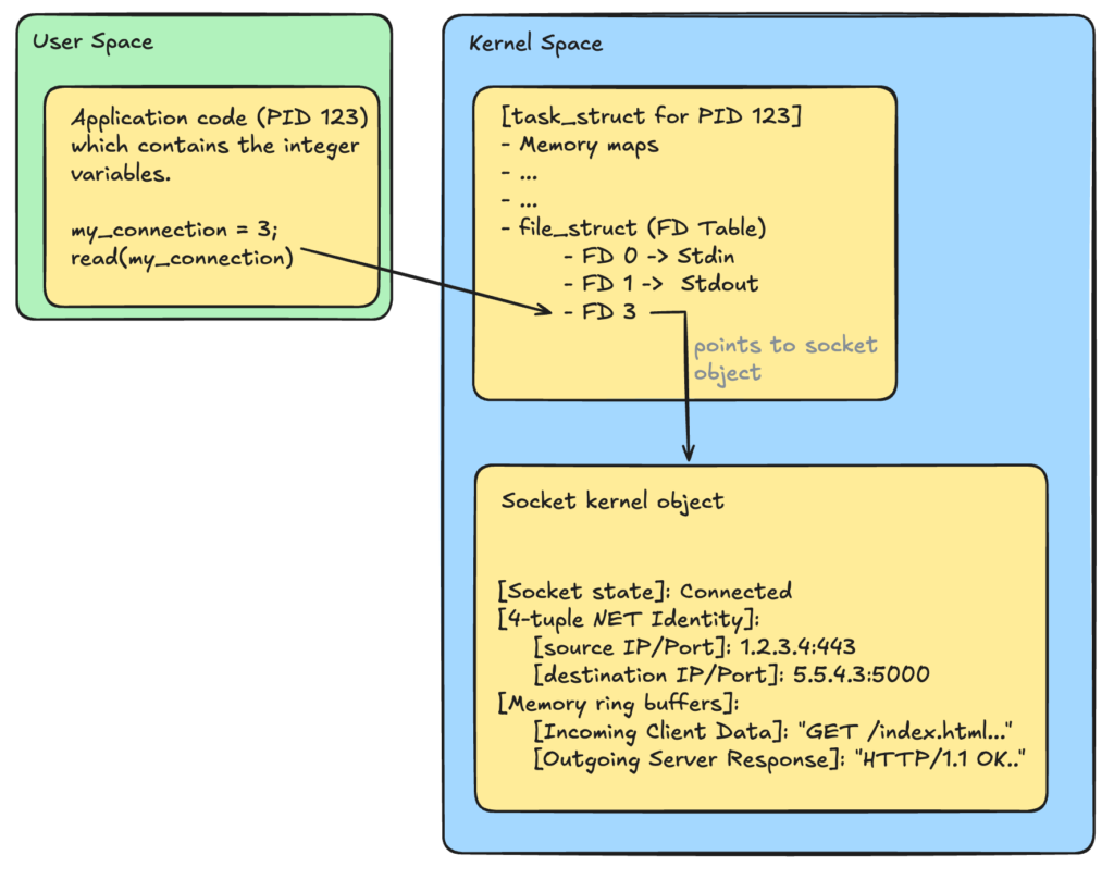
A socket is an object created in the linux kernel and tracks netowork connections. It acts as the kernel’s private spreadsheet, storing the connection’s unique 4-tuple identity ([Source IP, Source Port, Destination IP, Destination Port]), tracking its active TCP state machine phases, and housing the incoming and outgoing network data. Because user applications are forbidden from touching kernel memory directly for security and isolation reasons, the operating system generates a File Descriptor (FD). The file descriptor is a simple, non-negative integer pointer placed inside the application process’s private tracking table that maps directly to that specific kernel socket.
To the kernel, a socket is just a pipe that transfers bytes. The kernel will keep that socket alive until the application code explicitly tells it to close.
Let’s illustrate that in the following diagram:
TCP 3-way handshake connection establishment #
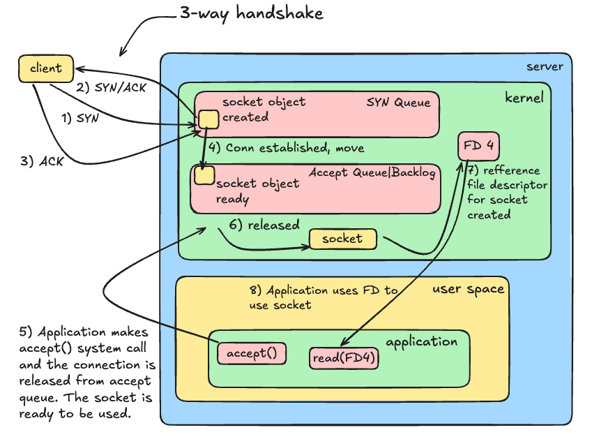
- Client sends SYN: The Linux kernel instantly allocates memory and spawns a Socket Object in the SYN_RECEIVED state. It places it into the SYN Queue.
- Server sends SYN-ACK: The server acknowledges the request and waits.
- Client sends ACK: The connection is now officially Established.
- The Queue Shift: The kernel immediately upgrades the existing socket’s status to ESTABLISHED and moves it from the SYN Queue into the Accept Queue.
- The Cap Check: The maximum number of sockets this Accept Queue can hold is dictated by the application’s configured Backlog limit (clamped by the kernel’s somaxconn ceiling).
- The App Delivery: Your backend application calls accept(), pops the completed socket out of the Accept Queue, generates a File Descriptor integer, and hands it to your application code logic to read the incoming HTTP data.
The True Math of Max Connections #
The maximum number of concurrent connections a server can handle is fundamentally determined by the number of open File Descriptors (FDs) allowed per application process.
Let’s trace a concrete example. Suppose your application is configured with a strict ceiling of 1,024 File Descriptors (ulimit -n), and your kernel accept queue is configured with a backlog cap of 500.
Under normal conditions, the application handles 1,024 sockets concurrently. As long as the code processes requests rapidly and executes a graceful close() in time, the incoming traffic is popped out of the line instantly. As a result, you will never run out of space in the accept queue, and the outside waiting line remains near zero.
However, if the application logic slows down, the active requests hang, but new clients keep arriving. The application continues calling accept(), assigning a fresh FD slot to each user, until all 1,024 File Descriptors are completely occupied.
At this point, the application hits its software wall. Because it cannot generate a new file descriptor, the application can no longer execute the accept() system call.
But the internet does not stop sending traffic. New clients continue executing the Layer 4 TCP 3-Way Handshake in the background. The Linux kernel completes these handshakes automatically and tries to push the established sockets into the Accept Queue. Because the application is frozen and cannot clear the front of the line, the queue backs up rapidly.
Once the accept queue hits its threshold of 500 connections, the server reaches total capacity. The next SYN packet sent by a client will be instantly blocked. Because there is no room left in either the SYN or the accept queue boundaries and the server starts to drop packets.
TCP Segments #
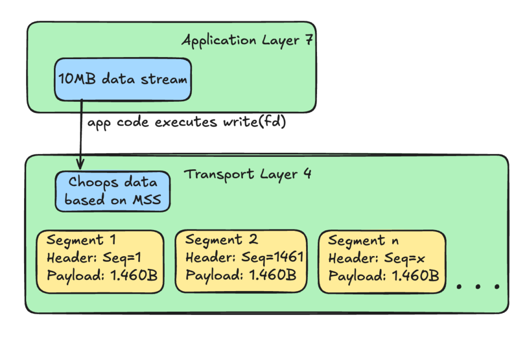
The application does not understand physical network limits. So if the application ties to upload a 10MB image it is pushing this entire chunk with the write(FD) system call.
However, physical network hardware (like Ethernet or Wi-Fi) has a strict limit on how large a single data transmission can be. This physical limit is called the MTU (Maximum Transmission Unit), and on almost all networks, it is 1,500 bytes.
The Linux kernel’s TCP engine intercepts the 10MB block and chops it into smaller pieces called Segments.
The kernel calculates the maximum size a segment can be without causing network issues and it is called MSS (Maximum Segment Size). Since the IP header is 20 bytes and the TCP header is 20 bytes, the MSS is 1,460 bytes of actual data per segment.
To ensure these segments can be tracked and reassembled on the other side, the TCP engine stamps a Sequence Number onto the TCP header of every single segment.
4-way handshake TCP connection termination #
When the application has sent the final byte of the response payload, and its configuration states it should not reuse the socket (for example a non-Keep-Alive connection or a Keep-Alive timeout has been reached), your application code triggers a close(fd) system call.
This initiates the 4-way handshake and this process is handled entirely by the client and server operating system kernels to ensure no data is cut off mid-transmission.
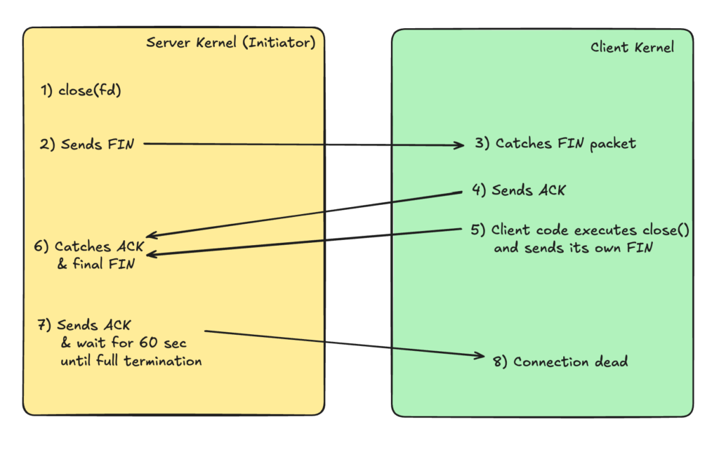
Why 4-way handshake?
When the server sends a FIN packet, the client will acknowledge and stop expecting new data from the server. However the clients might have remaining data that it needs to send to the server and when its ready the client will send its own FIN. Only then the server will know that now it can really kill the connection and like this we ensure no data is lost.
🔹 iptables & NAT #
iptables isn’t just a security firewall for dropping packets, but also a powerful router.
Prerouting chain & NAT tables #
It is also known as the Port Forwading, a type of Destination NAT (DNAT). Effectively the DNAT table. It intercepts an incoming packet before the kernel makes any routing decisions, changes the target destination IP and port, and forwards it along to the local process.
Let’s say your main router or host machine has a public IP of 203.0.113.50. Inside the private network you have a Docker container running a web server at a private IP of 172.17.0.2:8080 and you want anyone on the internet to be able to access your web server by typing your public IP on standard port 80.
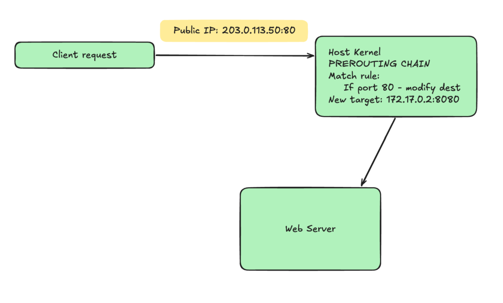
How this command would look like?
ptables \
--table nat \ #work on the nat table
--append PREROUTING \ #append rule to PREROUTING chain
--protocol tcp \ #match packets with TCP protocol
--dport 80 \ #match packet with destination port 80
--jump DNAT \
--to-destination 172.17.0.2:8080
When the server wants to reply back the the above client request, it cant reply to the client directly. It needs to send the request back to the router or the host server using the Postrouting chain.
Postrouting chain #
POSTROUTING catches packets right before they leave the network card. This is the place in the kernel where Source NAT (SNAT) and MASQUERADE take place.
This is basically when the web server on your private network with the private IP wants to reply back to the client that made the request through the router or the proxy host. What will be done is besically rewrite the source IP and/or port before the response goes out to the internet and replace it with the router’s public IP.
sudo iptables \
--table nat \
--append POSTROUTING \ #append to POSTROUTING chain
-o eth0 \
-j SNAT \
--to-source 203.0.113.50
L4 Load Balancing #
If you think of using a Layer 4 load balancing, you usually think of installing specialized software proxies like HAProxy, NGINX etc.
However, because Layer 4 balancing only requires inspecting routing data (IP addresses and TCP/UDP ports), you do not need to install any third-party software. The Linux kernel’s Netfilter engine can act as a Layer 4 load balancer using nothing but iptables.
In fact, this exact built-in kernel mechanism is how Kubernetes routes traffic to Pods under the hood when running in its default kube-proxy iptables mode.
🔹 DNS #
When we make a request www.example.com, you understand that we cannot initiate any connection using TCP or UDP since they expect an IP and a port in order to go down the OSI layers and go out to the internet.
For that reason we need to make a DNS request to find out the IP of a domain name. It is build on top of UDP for fast processing.
Lets see how it looks like and what are the components and routes of a single DNS call.
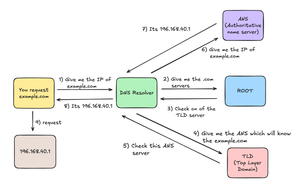
This is what happens when your client gets out to the internet and look for the IP of a domain name. Let’s look what is the flow inside the client’s machine before it goes out to look for the IP.
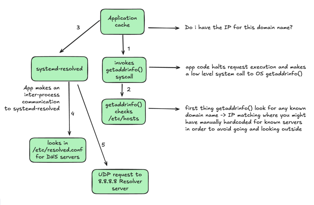
DNS Records
DNS records are data entries stored in a nameserver’s database. They function like a phonebook directory, mapping human-readable domain names to specific network destinations, mail routes, or text verification strings.
Here is the reference table of the core records:
| Type | What It Means | Core Use Case |
|---|---|---|
| A | IPv4 Address | Directs a domain name to a standard IPv4 cloud server or load balancer. |
| AAAA | IPv6 Address | Directs a domain name to a modern IPv6 network address endpoint. |
| CNAME | Canonical Name (Alias) | Creates an alias pointing one domain name to another domain (essential for CDNs). |
| MX | Mail Exchanger | Specifies the priority list of servers responsible for routing inbound emails for a domain. |
| TXT | Text String | Used for domain ownership verification and email security (SPF/DKIM/DMARC). |
| NS | Name Server | Delegates a domain zone to a specific authoritative manager. |
| SRV | Service Locator | Defines the exact host location and port number for specialized corporate network protocols. |
🔹 HTTPS & TLS #
I have extensively discussed this topic in my article: Understanding HTTPS & SSL Certificates


